Power-Up Problem with Cyclone
After building some boards with Cyclone EP1C6Q240C8 I experienced problems on some of them with startup.
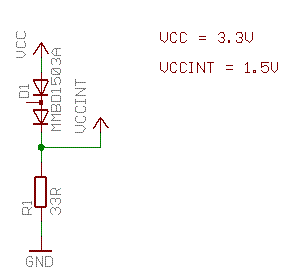
1.5V regulator
For the core voltage (1.5V) a synchronous step-down regulator from Linear Technology (LTC3405) is used. As described in Alteras application note (AN257).
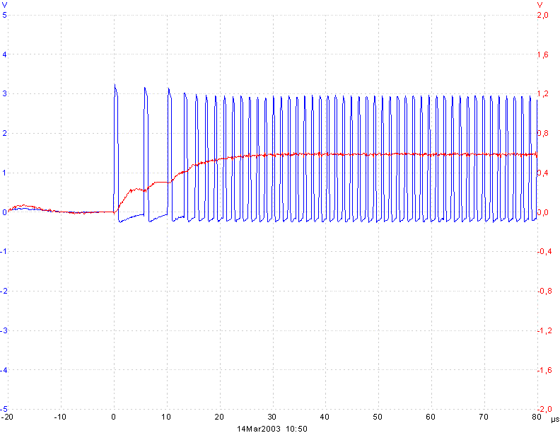
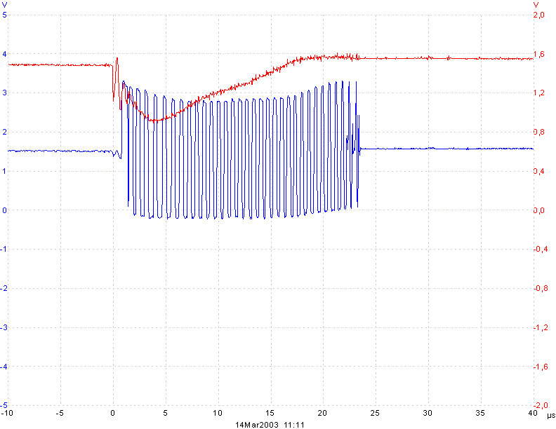
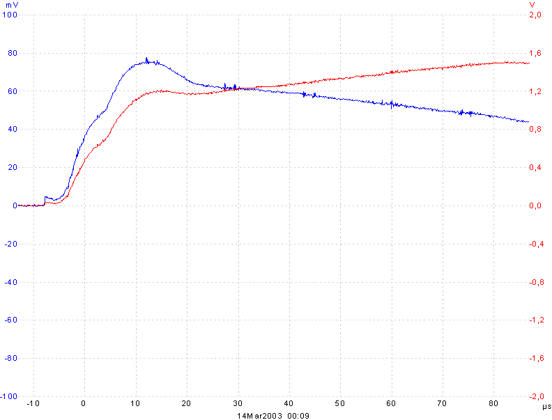
But the core voltage does not reach the 1.5V. The regulator stops at 0.5 - 0.8 V. I examined the problem by building an extern regulator.
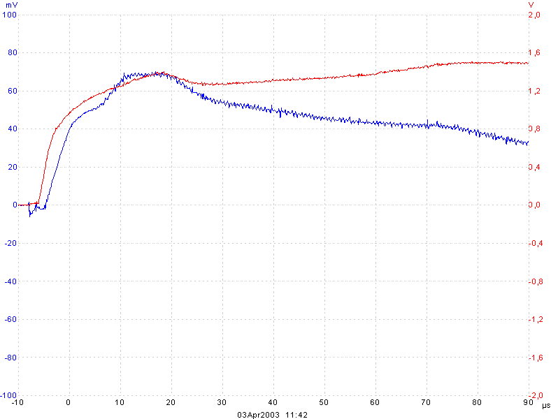
Red line is output voltage after the inductor on Cout(pin 5). Blue line is switching output of LTC3405 (pin 3).
For completeness: The current (blue) on the 1.5 V line measured with a 0.1 Ohm shunt and output voltage (red) as described later.
I have played around with different values for the inductor, but no chance.
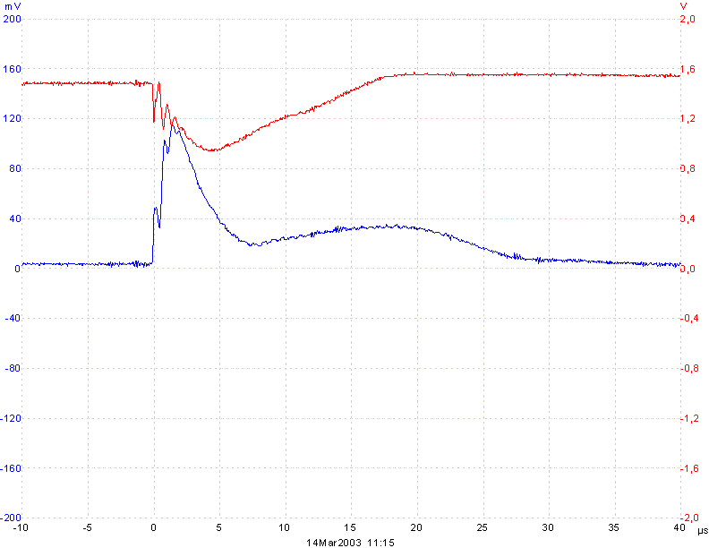
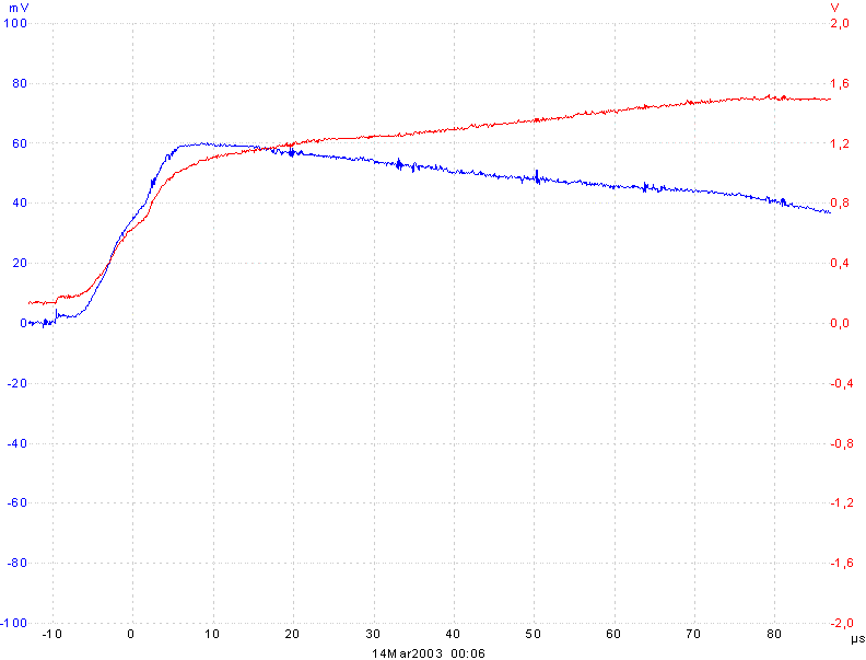
This is a picture of the regulator startup with a light load (resistor of 100 Ohm):
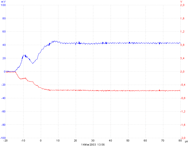
Starting the regulator without a load and then attaching the VCCINT (1.5 V) pins from
the Cyclone leads to a successfull start. The output capacitor (4u7) supplies
enough initial current.
Red line is again the output voltage and blue the switching output.
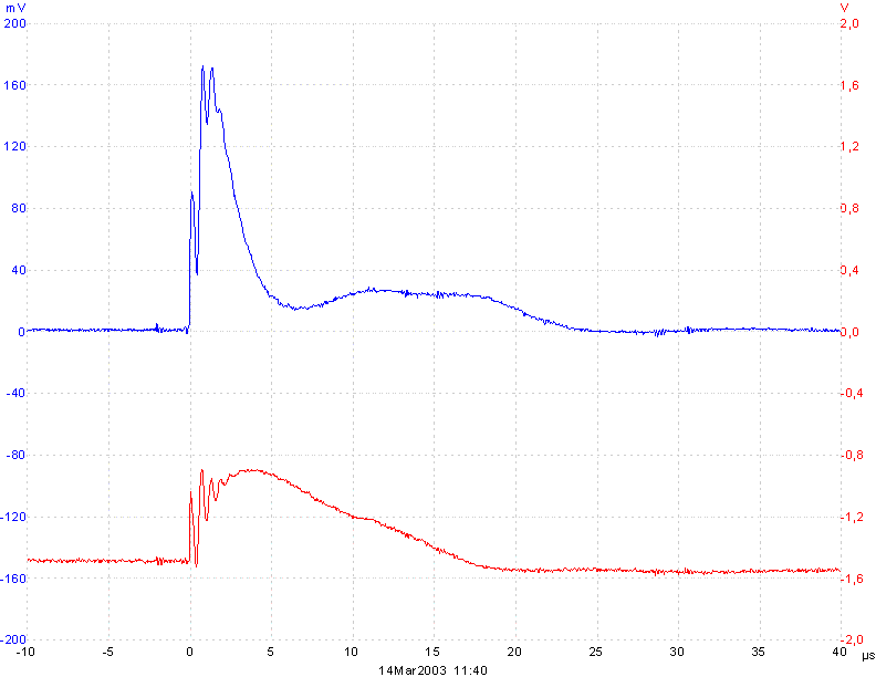
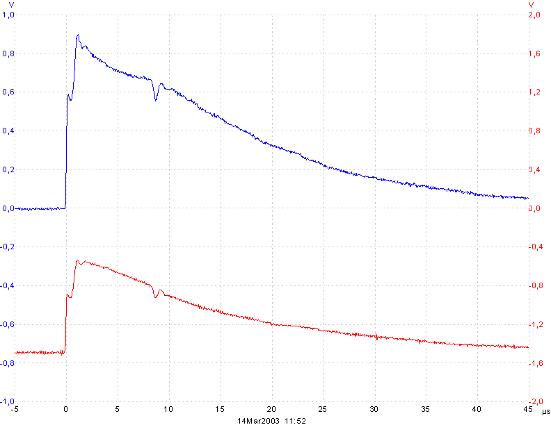
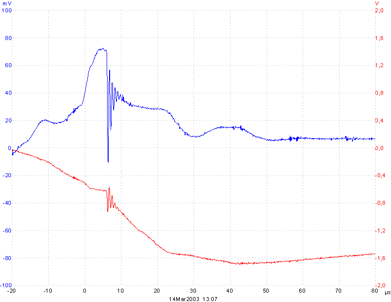
Measuring the current during startup yields to following results: First few us the Cyclone takes about 1.1A! Falling down to 350 mA and staying there for about 15 us (I think for internal startup). After that it dropps to a few mA. The LCT3405 is a 300 mA regulator with a peak current of about 650 mA. It can not deliver this peak current during it's own start.
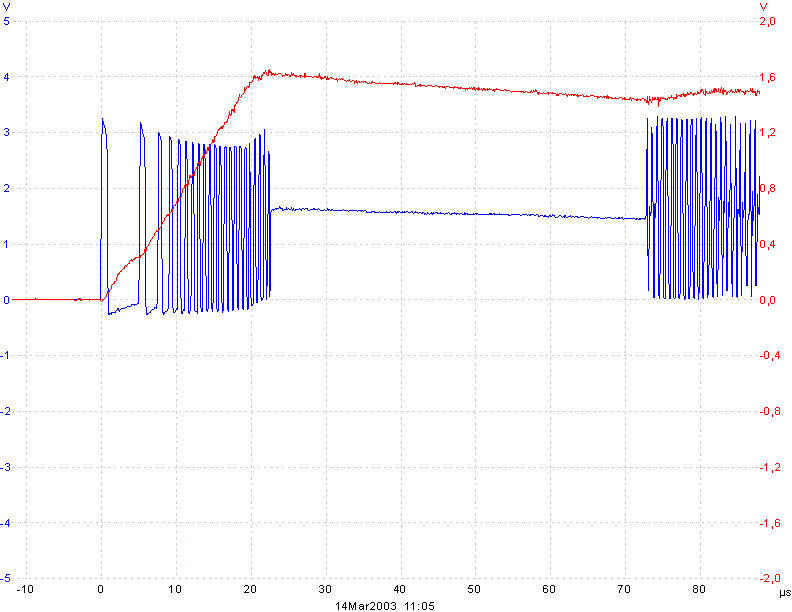
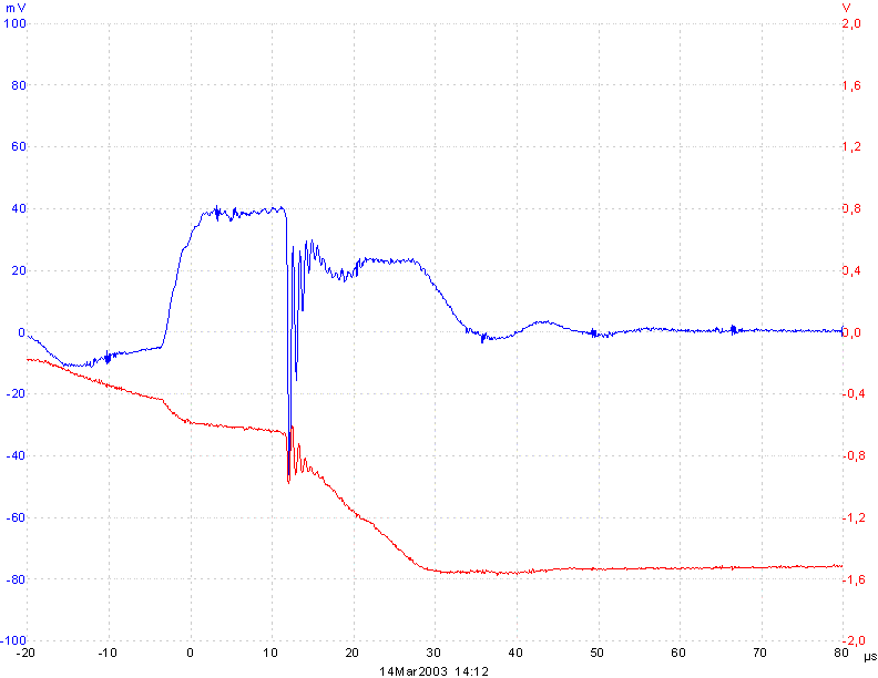
Following picture shows startup input current on VCCINT (blue line). VCC is allready on 3.3V. The current is measured with a 0.1 Ohm shunt. Red line is again VCCINT.
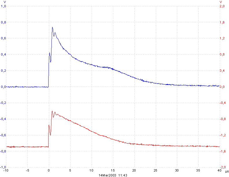
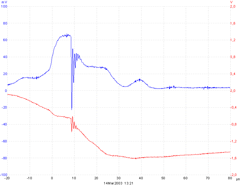
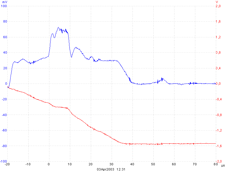
The above plot was captured with the shunt in the GND line. To make shure that I have not measured some current from the 3.3V (VCC) the following plot shows a different setup. The shunt is in the 1.5V line. VCCINT is measured 'reverse'. The peak is still very large.
I think the Cyclone takes all current it gets in the first us. But is this large current neccessary for startup?
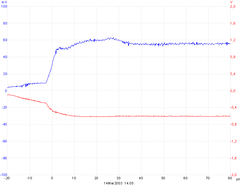
Increasing the shunt to 1 Ohm reduces the peak current to about 0.65A and the startup is still successfull.
With a 2.2 Ohm shunt the current can be reduced to 360 mA with a successfull startup.
I got following information from Altera:
The highest power-up current requirement that we have characterized for the Cyclone family is 420 mA. This is more than the LTC3405 can supply, and we are modifying AN257 accordingly.
Considering this it is necessary to build a curcuit to 'help' the LTC3405 at startup.
Simulation to find a Solution
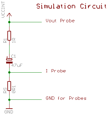
After a long discussion in comp.arch.fpga I tried some of the suggestions. To test the different 'helper' circuits I modeled the start-up current of the Cyclone VCCINT. The model is very simple and a worse case than the actual Cyclone:
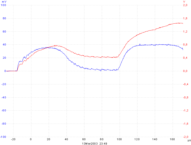
For all following pictures: Red line is VCCINT and blue line current on a 0.1 Ohm shunt.
The step-down regulator without startup help
It can be seen that the regulator stops startup at about 350 mA and 0.8 V. It detects a short circuit and reduces switching frequency. Later it starts again and reaches the output voltage. But this is an effect of the simple simulation model. Cyclone draws large current at 0.8 V.
Two diodes and an additional 22 Ohm resistor
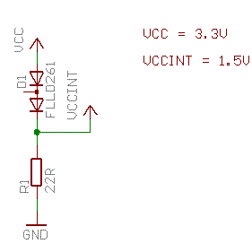
The diodes deliver additional 'charge' from the 3.3 V.
R1 is necessary to keep Ud at more than 0.9 V when the Cyclone is not running.
This circuit can deliver a peak current of 0.75 A at a pretty fast rise time.
Two low leakage diodes and an additional 33 Ohm resistor
Same circuit as above, but with different typ of diodes. Peak current is 0.6 A.
Vbe Multiplier
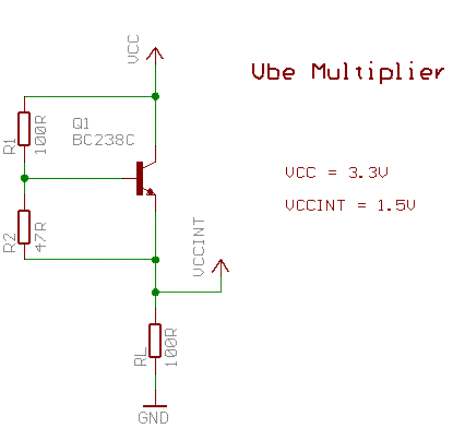
Like the simple diode circuits a load resistor (RL) is necessary.
But only 15 mA 'waste'.
The transistor delivers 200 mA at about 0.3 V, but with a slow rise time.
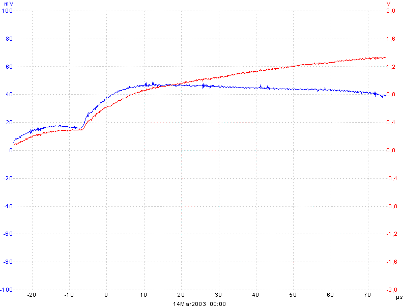
Simple Regulator
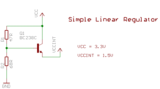
This circuit perfroms better than the Vbe mulitplier. 250 mA at 0.4 V and no RL.
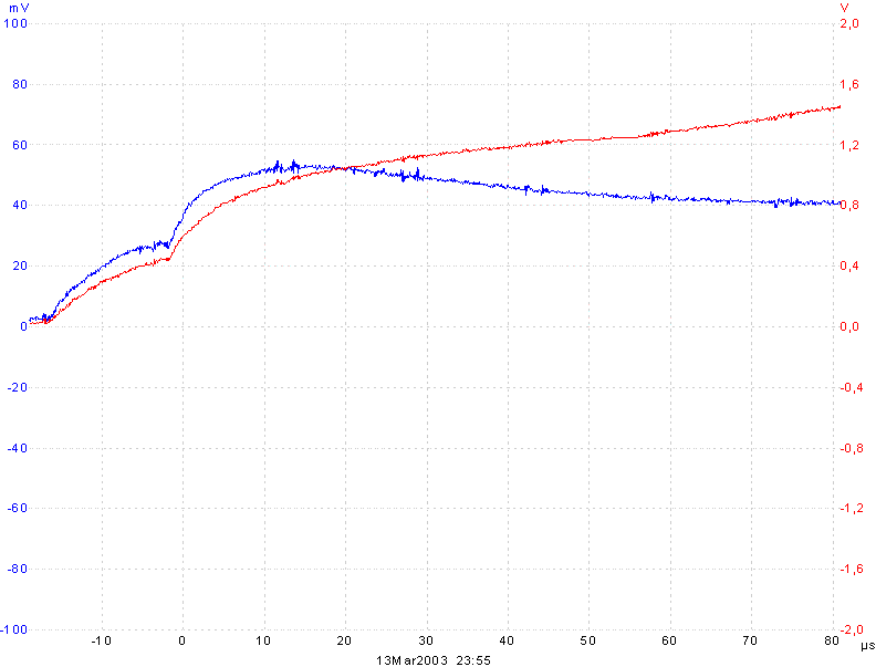
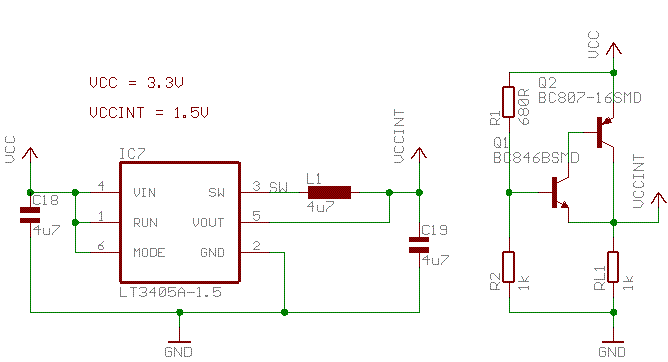
Simple Regulator with Darlington
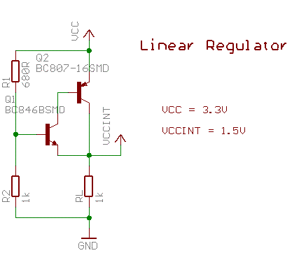
The darlington pair can deliver 500 mA at 1.2 V. A load of 1K is necessary to prevent the output from rising above 1.5 V.
Testing the Circuits with the Cyclone
The above circuits where tested with the Cyclone. Current (blue) was measured with the 0.1 Ohm shunt in the VCCINT line.The probe is connected as follows: GND of probes on VCCINT (at Cyclone). Probe 1 (blue) at the point between shunt and output of the regulator. Probe 2 (reg) at GND of the Cyclone (resulting in negativ plots).
Two diodes and an additional 22 Ohm resistor
Two low leakage diodes and an additional 33 Ohm resistor
Vbe Multiplier
This circuit delivers to less current or is to slow to help the regulator.
Simple Regulator
Simple Regulator with Darlington
Conclusion
The simple diodes from 3.3V provide large current for the Cyclone in the first us. Enough headroom, but some 'waste' is necessary.The darlington regulator circuit performs better and needs less standby current. But 5 additional components.
I selected the darlington circiut.
Power usage of the Cyclone
I measured for a 'started' and not yet configured Cyclone a standby current of 26 mA.Loaded with JOP (about 2500 LEs with 1200 FFs) running at 20 MHz an EP1C6Q240C8 needs about 54 mA (VCCINT).
Acknowledgements
Most of the ideas came from a discussion at comp.arch.fpga. I would like to thank:- Jonathan Bromley
- Jim Granville
Contact
If you have additional comments about this problem pleas drop me a note: martin.schoeberl@chello.atI will include it on this site. Also let me know if one of the solutions works for you.